Radiologia Brasileira - Publicação Científica Oficial do Colégio Brasileiro de Radiologia
AMB - Associação Médica Brasileira CNA - Comissão Nacional de Acreditação
 Vol. 44 nº 4 - July / Aug. of 2011
|
REVIEW ARTICLES
|
|
Radiological propedeutics of femoroacetabular impingement in times of computed tomography and magnetic resonance imaging: what a radiologist needs to know |
|
|
Autho(rs): Rafael Borges Nunes1; Denise Tokechi Amaral2; Valesca Sarkis de Oliveira3 |
|
|
Keywords: Femoroacetabular impingement; Conventional radiology; Computed tomography; Magnetic resonance imaging; Radiological propedeutics. |
|
|
Abstract: INTRODUCTION
From the biomechanical point of view, the hip is a complex joint and is subjected to constant stress on account of bearing the body weight. It can be affected by congenital, degenerative, inflammatory, traumatic and neoplastic disorders, and in many circumstances, surgery is included in the therapeutics(1). Over the last decades, the imaging evaluation of such joint has showed great developments, especially with the advent of multidetector computed tomography (MDCT) and high-field magnetic resonance imaging (MRI). The use of 3D and multiplanar reconstruction provided by MDCT and the performance of magnetic resonance arthrography (MRA) provide important information for the management of disorders of the hip, which in the past were not part of the daily activities of the radiologist. Moreover, with the development of arthroscopic procedures in the last decade, the imaging evaluation of this joint has undergone a major learning curve. However, in times of latest generation apparatuses, conventional radiology remains as a cornerstone, with its use in association with other imaging methods posing a challenge to radiologists. In such a context, a protocol for imaging evaluations of the hip has been established, as a result of joint efforts with some reference orthopedic centers over the past eight years. CONCEPTS Femoroacetabular impingement The main function of the acetabular labrum is to exert a negative intra-articular pressure, allowing a homogeneous distribution of the intra-articular fluid, with increased joint lubrication, preventing the direct contact between articular surfaces and distributing the force applied on the hyaline cartilage. The anterior and antero-superior portions of the chondrolabral junction present a greater predisposition to labral injuries, with possible causes being the great mechanical demand and the hypovascularization of the labrum in this region. With the labral tear, a biomechanical change of the hip occurs, determining chondral erosion(2) and triggering the joint degeneration process. Among the causes of labral injuries, femoroacetabular impingement (FAI) is highlighted, and it can be divided into two types: pincer and cam. The pincer type is a consequence of the repetitive impact between the acetabular labrum and the femoral head/neck junction in the presence of acetabular overcoverage (acetabular retroversion, and coxa profunda/protrusio), the labrum being the most vulnerable structure in the physiopathological chain(3). It predominates in the age group between 20 and 40 years, particularly in women, or in young women at early stages of sport activities. Among the causes of acetabular protrusion one can also mention: osteoporosis, osteomalacia, osteogenesis imperfecta, rheumatoid arthritis, Pagets disease, hypophosphatemia, or may be idiopathic (Otto pelvis)(4). The cam type is related to loss of femoral head/neck junction concavity, determining impact on the antero-superior portion of the acetabular cartilage, followed by chondral erosion and adjacent labral detachment. Such concavity loss is also observed in cases of epiphysiolysis of the femoral head, Legg-Calvé-Perthes syndrome and femoral neck fracture(4,5). Conventional radiology The following radiographic views can be utilized in the propedeutics of FAI: a) frontal pelvic view in dorsal decubitus and orthostatic position; b) Lauenstein view; c) faux profile of Lequesne; d) Ducroquet view ; e) cross table view or Arcelins surgical profile; f) Dunn view. a) Frontal pelvic view in dorsal decubitus and orthostatic position The patient is placed in orthostasis, with internal rotation of the feet (approximately 15º) with the imaging centered at 2 cm above the pubic symphysis(6). The internal rotation is necessary to avoid the superimposition of the femoral neck by the greater trochanter. The obturator foramina and the iliac wings must be symmetrically positioned(7) with the coccyx aligned with the symphysis at a maximum 2.5 cm distance from each other (Figure 1). 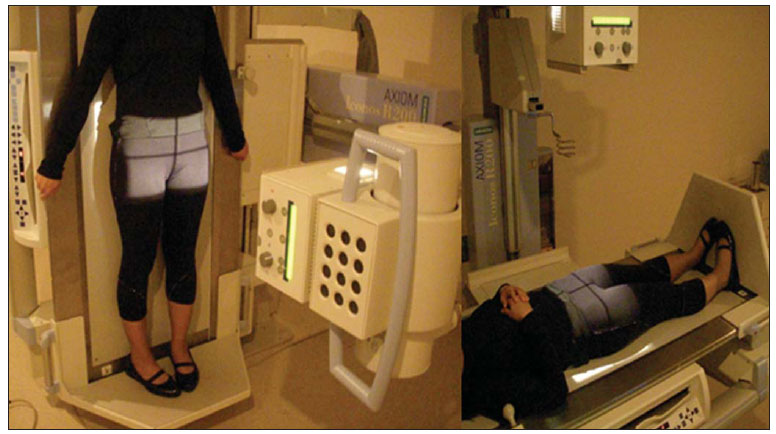 Figure 1. Anteroposterior radiography, centered at 2 cm above the pubic symphysis, with internal rotation of the lower limbs. On this view, collodiaphyseal angle, acetabular coverage angle, coxa profunda, acetabular retroversion and femoral head/neck junction are evaluated. The collodiaphyseal angle is formed by the intersection between the lines along the axis of the neck and of the femoral diaphysis (normal value = 125 to 140º; > 140º, coxa valga; < 125º, coxa vara). The acetabular coverage angle is formed by the intersection between two lines from the center of the femoral head, one of them perpendicular and the other tangent to the acetabular rim (normal value = 20 to 40º; > 40º, it indicates acetabular overcoverage; from 20 to 25%, coverage deficit; < 20%, acetabular dysplasia) (Figure 2). 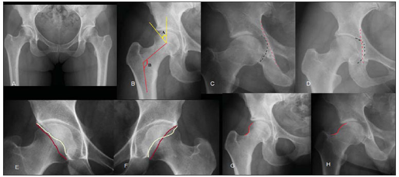 Figure 2. A: Frontal radiography of the hip. B: In yellow, acetabular coverage angle (A), and in red (B), collodiaphyseal angle. C: In the normal hip, the acetabular bottom (represented by the black dashed line) does not medially overcome the ischial line (red dashed line). D: In cases of coxa profunda, the acetabular bottom is medially projected towards the ilioischial line. E: In normal hip, the yellow line (drawn over the anterior acetabular rim) is medially projected towards the red line (posterior rim). F: At acetabular retroversion, there is an intersection between the lines, known as the eight sign or crossing sign. G: Femoral head/neck junction with normal appearance. H: Loss of habitual concavity of the femoral head/neck junction, found in cases of cam type impingement. b) Lauenstein view Patient in dorsal decubitus, in abduction and maximum external rotation of the hips, with juxtaposed feet soles. The main objective is the evaluation of the antero-superior portion of the femoral head, in cases where subchondral fractures or osteonecrosis are suspected(8) (Figure 3). 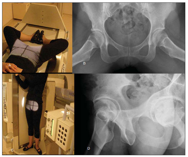 Figure 3. Lauenstein positioning (A) and view (B). Lequesne positioning (C) and view (D). c) Faux profile of Lequesne The patient is placed in orthostasis, with the hip of interest close to the chassis. The line between the patients shoulders must be angled at 65º and the foot at the side of interest must be parallel to the chassis. In order to know whether the imaging was properly positioned, there must be a distance corresponding to one femoral head between the two heads(7). This view allows the evaluation of the articular space in the anterior and posterior compartments(6,7) (Figure 3). d) Ducroquet view Patient in dorsal decubitus, with the hips flexed at 90º and abducted at 45º, with the central beam perpendicular to the thighs root. On this view, it is possible to evaluate the loss of concavity in the anterior portion of the femoral head/neck junction in cases of CAM impingement (Figure 4). 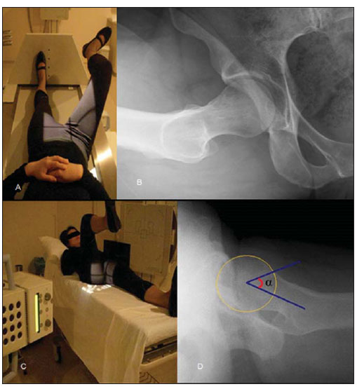 Figure 4. Ducroquet positioning (A) and view (B). Cross-table positioning (C) and view (D), with demonstration of the alpha angle (α). e) Cross table view or Arcelins surgical profile Patient in dorsal decubitus, with the lower limb of interest fully extended and maximum contralateral flexion, with a focus-film distance of approximately 1.2 m and the horizontal beam angled at 45º cephalic, centered on the thighs root(7). Such a view is critical in the study of cam type impingement, for the evaluation of the anterior portion of the femoral head/neck junction, with calculation of the alpha angle in dubious cases. For calculation of the alpha angle: a circle is drawn on the femoral head; from the center of this circle, two lines are drawn, one in the direction of the femoral neck axis and the other to the point where the cortex of the anterior portion of the head/neck junction looses contact with the circle (Figure 4) (normal value < 55º)(6). f) Dunn view Dunn view is a variation of the Ducroquets view, performed with the patient in orthostasis, with the hips flexed at 45º and abducted at 20º, with central beam perpendicular to the thighs root (Figure 5). It is useful in the evaluation of the antero-superior portion of the femoral head/neck junction. 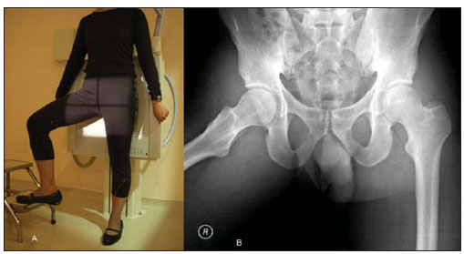 Figure 5. Dunn positioning (A) and radiographic view (B). Computed tomography Tomographic images are acquired in multidetector apparatuses, with subsequent reconstruction on workstations, with multiplanar (coronal, sagittal, oblique and axial) reconstructions. The reconstruction in the oblique sagittal plane allows a better evaluation of the femoral head/neck junction (Figure 6). At the 3D reconstruction, the disarticulation of the hip is performed, thus individualizing both the femur and the acetabulum, documenting them with 45º rotation. This provides the orthopedist with a three-dimensional perception of the changes in the joint, allowing a better understanding of such changes and better preoperative planning (Figure 6). 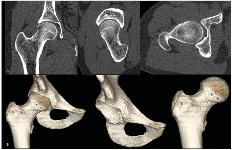 Figure 6. A: Multiplanar reconstruction in coronal, sagittal oblique and axial planes, respectively. B: 3D reconstruction before and after hip disarticulation. Magnetic resonance imaging Technical considerations Magnetic resonance imaging is the method of choice for the evaluation of muscles, tendons, ligaments, acetabular labrum and cartilage. At the authors institution, the images are acquired in a with 1.5 and 3 tesla magnet with coronal T1 fast spin-echo (FSE), axial/coronal/sagittal T2 and sagittal oblique proton-density (PD) sequences with fat saturation (with slices oriented by the longest axis of the femoral neck based on the scout view in the coronal plane) (Figure 7). The authors experience indicates that the sagittal oblique sequence has been the best one for the evaluation of labral injuries. 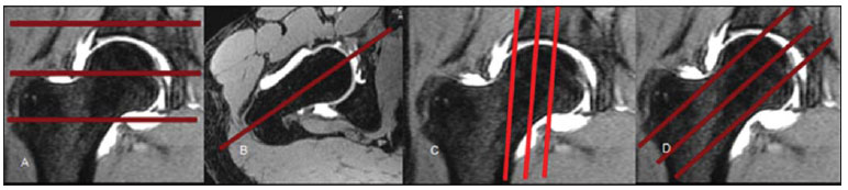 Figure 7. MRI section planes positioning: axial (A), coronal (B), direct sagittal (C) and sagittal oblique (D). The algorithm for evaluation by MRI must start by the conventional examination, with MRI arthrography being reserved for dubious cases, where clinical-radiological dissociation is observed or with the purpose of therapeutic evidence in the differentiation between intra and extra-articular pain. At MRI arthrography, the joint puncture is guided by radioscopy, by inserting the needle at 90º, towards the superolateral quadrant of the femoral head/neck junction(8). It can also be performed either with ultrasonography or CT guidance. A solution containing iodinated contrast agent, anesthetics (bupivacaine/Marcaine®), distilled water and paramagnetic contrast at 0.2 mmol/l (0.1 ml in 20 ml solution)(9) is injected into the joint. A maneuver to evaluate the presence of impingement is always performed before and after the intra-articular injection, with flexion, abduction and internal rotation of the hip. Improvement of the pain after anesthetic injection indicates that such a pain is of intra-articular origin. However, if no pain improvement is observed, such a possibility is not ruled out in the ongoing investigation(9). The MRI arthrography protocol consists of FSE sequences with fat saturation (axial/coronal T1-weighted, axial/sagittal T2-weighted and sagittal oblique DP sequences) and coronal T1-weighted sequence without fat saturation. Fat saturation increases the contrast between the intra-articular gadolinium and adjacent soft tissues(10). IMAGING PROPEDEUTICS IN CHONDRAL AND ACETABULAR LABRUM LESIONS The normal acetabular labrum is characterized by its triangular shape, presenting low signal intensity on all sequences(11). Eventually, a labral cleft may be observed, filled by the contrast medium. Such a finding should not be confused with a tear. Labral clefts have been described at several locations, with higher prevalence at the lower and posterosuperior quadrants(12,13) (Figure 8). Clefts at the posterosuperior portions may be prominent and must be differentiated from labral tears, being characterized by hypersignal on T2-weighted sequences or contrast medium interposition with a linear form with regular margins, and adjacent labrum with preserved morphology(12). 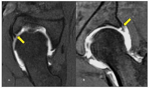 Figure 8. Antero-inferior (A) and postero-superior (B) sublabral clefts. On the other hand, labral tears are characterized by the irregular contrast medium interposition in the chondrolabral interface, being transfixed by the probe, possibly in association with intra-or perilabral cysts(11) (Figure 9). 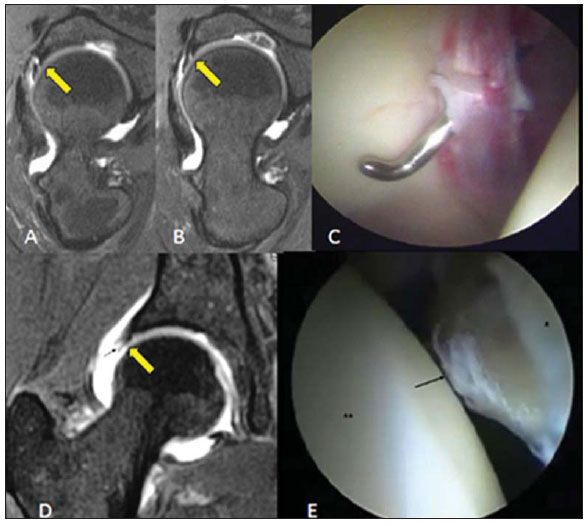 Figure 9. A,B: Chondrolabral junction tear at the antero-superior portion of the acetabular labrum (arrow), filled by contrast medium at MRI arthrography, sagittal oblique plane. C: At arthroscopy, the labrum is devitalized, with a purplish color, being transfixed by the probe. D: Degenerative changes at the acetabular labrum, with fissures in the substance and fringed appearance at arthroscopy (E). In spite of the small thickness of the cartilage lining the hip joint, it is of utmost importance to measure chondral lesions associated with labral tears(14), as the decision making on the approach as well as the therapeutic success depend on the extent of the chondral involvement (Figure 10). 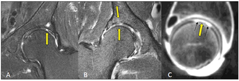 Figure 10. A: Focal and deep chondral erosion with bone exposure and development of subchondral cyst at the acetabular roof. B: Thinning and diffuse irregularity of the lining cartilage of both joint components, with acetabular bone marrow edema. C: CT arthrography demonstrating deep chondral erosion on the femoral head, filled by contrast medium. CONCLUSION The imaging evaluation of the hip has gone through many changes over the past decade, particularly after the advent of arthroscopic procedures. The radiologist must be familiar with the biomechanics and physiopathology of the femoroacetabular impingement and must know the imaging propedeutics of the joint. Acknowledgement To Dr. Giancarlo Polesello, for providing the arthroscopic images. REFERENCES 1. Fishman EK, Magid D, Mandelbaum BR, et al. Multiplanar (MPR) imaging of the hip. Radiographics. 1986;6:7-54. 2. McCarthy JC, Noble PC, Schuck MR, et al. The watershed labral lesion: its relationship to early arthritis of the hip. J Arthroplasty. 2001;16(8Suppl1):81-7. 3. Siebenrock KA, Schoeniger R, Ganz R. Anterior femoro-acetabular impingement due to acetabular retroversion. Treatment with periacetabular osteotomy. J Bone Joint Surg Am. 2003;85-A:278-86. 4. Beall DP, Sweet CF, Martin HD, et al. Imaging findings of femoroacetabular impingement syndrome. Skeletal Radiol. 2005;34:691-701. 5. Ito K, Leunig M, Ganz R. Histopathologic features of the acetabular labrum in femoroacetabular impingement. Clin Orthop Relat Res. 2004;(429):262-71. 6. Tannast M, Siebenrock KA, Anderson SE. Femoroacetabular impingement: radiographic diagnosis - what the radiologist should know. AJR Am J Roentgenol. 2007;188:1540-52. 7. Godefroy D, Chevrot A, Morvan G, et al. Les clichés simples du bassin. J Radiol. 2008;89:679-91. 8. Crim J, Morrison WB. Hip procedures. In: Crim J, Morrison WB, editors. Specialty imagingTM. Arthrography: principles and practice in radiology. 1st ed. Philadelphia, PA: Amirsys; 2009. p. 130-3. 9. Fitzgerald RH Jr. Acetabular labrum tears. Diagnosis and treatment. Clin Orthop Relat Res. 1995;(311):60-8. 10. Chan YS, Lien LC, Hsu HL, et al. Evaluating hip labral tears using magnetic resonance arthrography: a prospective study comparing hip arthroscopy and magnetic resonance arthrography diagnosis. Arthroscopy. 2005;21:1250. 11. Petersilge CA. From the RSNA Refresher Courses. Radiological Society of North America. Chronic adult hip pain: MR arthrography of the hip. Radiographics. 2000;20SpecNo:S43-S52. 12. Studler U, Kalberer F, Leunig M, et al. MR arthrography of the hip: differentiation between an anterior sublabral recess as a normal variant and a labral tear. Radiology. 2008;249:947-54. 13. Saddik D, Troupis J, Tirman P, et al. Prevalence and location of acetabular sublabral sulci at hip arthroscopy with retrospective MRI review. AJR Am J Roentgenol. 2006;187:W507-11. 14. Schmid MR, Nötzli HP, Zanetti M, et al. Cartilage lesions in the hip: diagnostic effectiveness of MR arthrography. Radiology. 2003;226:382-6. 1. Titular Member of Colégio Brasileiro de Radiologia e Diagnóstico por Imagem (CBR), Fellowship in Musculoskeletal Imaging at Med Imagem Diagnósticos por Imagem, Hospital Beneficência Portuguesa de São Paulo, São Paulo, SP, Brazil. 2. PhD, Titular Member of Colégio Brasileiro de Radiologia e Diagnóstico por Imagem (CBR), Musculoskeletal Radiologist at Med Imagem Diagnósticos por Imagem, Hospital Beneficência Portuguesa de São Paulo, São Paulo, SP, Brazil. 3. Titular Member of Colégio Brasileiro de Radiologia e Diagnóstico por Imagem (CBR), Musculoskeletal Radiologist at Med Imagem Diagnósticos por Imagem, Hospital Beneficência Portuguesa de São Paulo, São Paulo, SP, Brazil. Mailing Address: Dr. Rafael Borges Nunes Rua José Getúlio, 192, ap. 303, Liberdade São Paulo, SP, Brazil, 01509-000 E-mail: rafaufpa@yahoo.com.br Received November 15, 2010. Accepted after revision March 15, 2011. Study developed at Med Imagem Diagnósticos por Imagem, Hospital Beneficência Portuguesa de São Paulo, São Paulo, SP, Brazil. |
|
Av. Paulista, 37 - 7° andar - Conj. 71 - CEP 01311-902 - São Paulo - SP - Brazil - Phone: (11) 3372-4544 - Fax: (11) 3372-4554